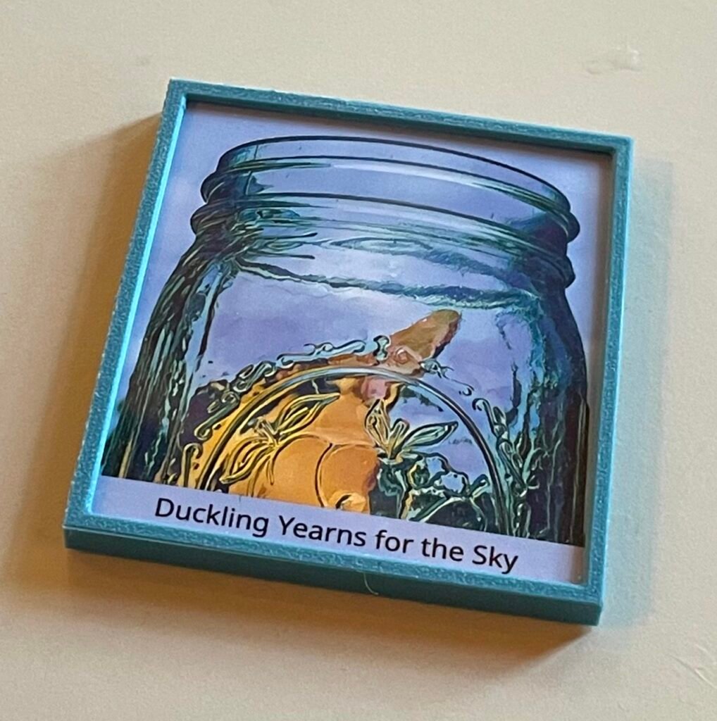
I’ve been using the other 3D-printed magnetic frames described earlier, to create prints to put in my FLAG and mail to others. But I’ve noticed these tend to get sun-faded if they’re out for long, and even if the photo paper is glued down, it gets ripply.
This might be largely because I’m in Louisiana, where the sun is bright and the air is moist. But at any rate, I wanted a way to frame things that was a step up in durability. And that meant putting some kind of protection over the picture. Here’s my new design to accomplish that.


The goals of this design are:
- To have a plexiglass front to keep the artwork in place and flat, and to prevent fading.
- To have an optional aperture in the back.
- To control the placement, shape and size of raised areas to glue magnets on the back.
- If you choose to print the frame in clear material, allow for wrapped edges that are visible through the sides.
- To be able to custom-fit the frame to the artwork.
- To have it all snap together snugly with no glue, with the option to glue it if desired.
- Easy to print.
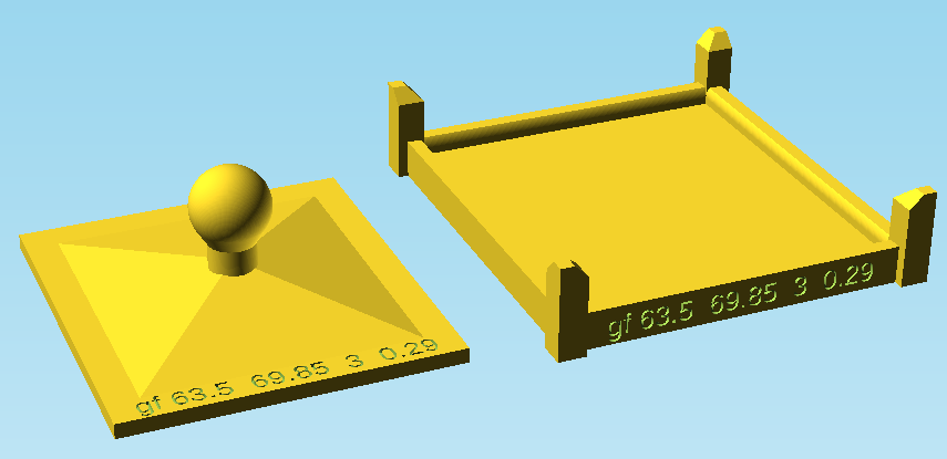
Frame assembly
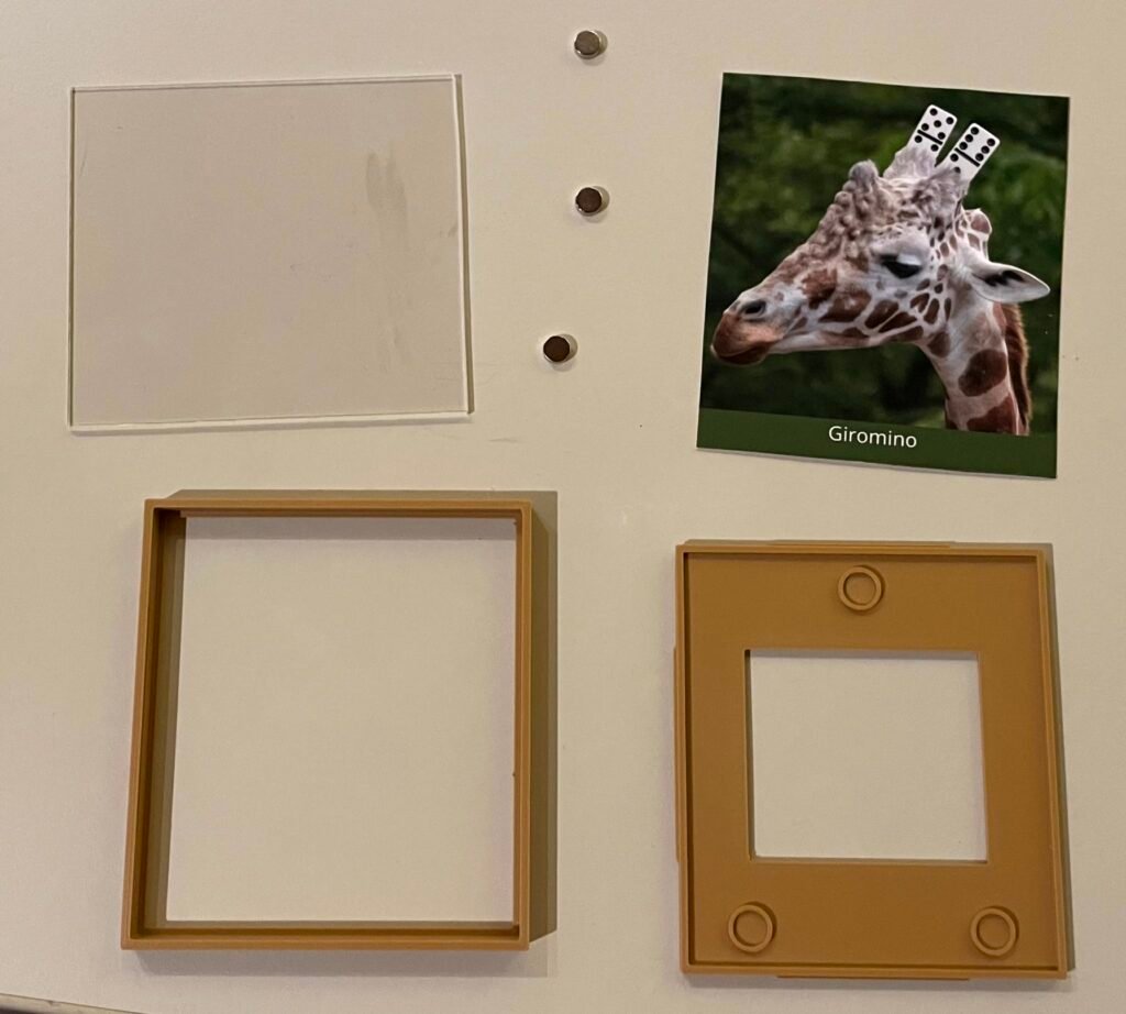
The frame has two parts you 3D-print — the outer frame, and the back.
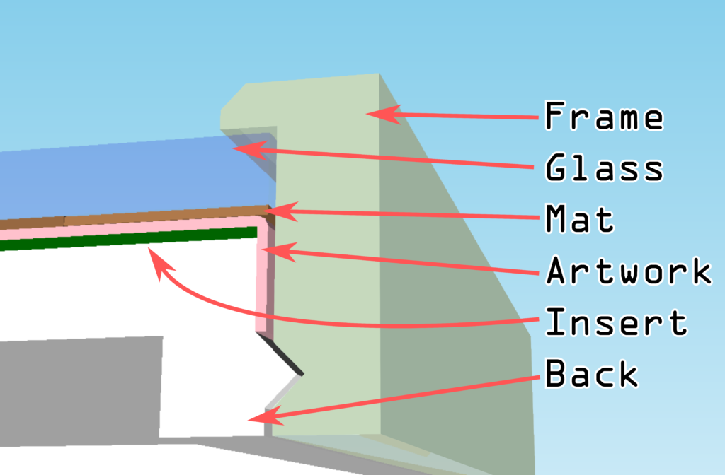
Then there’s the stuff you add, all of which is optional. That includes:
- Glass or plexiglass
- A mat or other material in front of the artwork
- Some artwork that optionally wraps around the edges
- An insert to go behind the artwork to be visible through the (optional) aperture in the back
To make it all snap together snugly, you must specify the dimensions of these items fairly precisely. The glass needs to fit under the overhang tightly enough to provide structural support and not pop out. There must be enough gap on the sides to support the wrapped-over edge, if any. The frame must be tall enough for the wrap to not interfere with the interlocking ridge. And so on.
If you measure accurately and enter the figures correctly, assembly should be a snap. Put the glass into the frame first. Arrange the other pieces onto the back in the desired order, using a little two-sided tape if there are layers smaller than the glass that might shift, and smoosh ’em together.
Preparing the plexiglass
For my examples, I went to Michael’s and got a 11″x14″ sheet of thin acrylic (1.4mm), which I cut into rectangles. It’s a challenge to do this precisely and get all the sides straight and the pieces the same size. I used a mat cutter to hold the acrylic in place at the right position, using the metal rail as a guide while I score the acrylic with a box cutter. (I don’t think a mat cutter blade is durable enough for acrylic, and depending what kind of cutter you have, it’s a challenge to keep the blade steady when it can’t actually cut into the material.)
Once you’ve scored it two or three times with authority, you should be able to snap the material cleanly.
Depending how steady your hand is, there may be some variability in these hand-cut pieces. You may want to measure them individually before you print the frames you’re going to put them into, and adjust the size parameters accordingly. If you plan to make a lot of these, of course, making the sizes precise so they will all fit your one size of frame is the easier way to go.
Don’t remove the protective film until you’re ready to put pieces into the frame, and then try to handle it by the edges to avoid smudging. When you snap a piece off, you will only have cut through the protection layer on one side, so it’ll start to peel on the other side. Keep a scissors or knife handy to cut the back protective layer along the break line, and smooth it back into place.
If you have access to a CNC cutting machine or water cutter, you can make precise cuts more easily with that. I’ve also been seeing ads for a tiny cute table saw, because Meta knows too much about me.
I would not advise cutting this type of acrylic with a laser cutter/engraver. Because it’s pretty transparent, much of the light just goes right through, so you need a powerful laser to deliver much heat to the material (5.5W wasn’t enough, 30W was). Then the edges tend to bump out a little from melted material oozing out of the cut path. I’ve had good luck using a laser with thicker, high-quality material, but not this stuff.
Another option is to order custom-cut pieces from a company that does that. I’ve done a little searching online and so far everything I’ve found is at least 3 times the cost of acrylic sheets from Michael’s, even for quantity pricing, e.g. $1.00 each for 3×4″ pieces. Depending how you value your time, it might be worth it — or if you find something better, please mention it in the comments.
Using the script
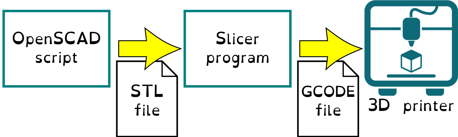
Here’s the script you would open in the OpenSCAD client to create this model.
This script assumes you have the BOSL2 library installed. I’ve written elsewhere about how to use OpenSCAD generally, including about this library, so I won’t repeat that here. Instead I’ll just discuss the various Customizer parameters and their effects.
There are a fair number of settings for this frame, supporting a lot of different ways to customize it. I expect you’ll have just a few different sizes and styles of frame you’ll use many times, so if you get the settings right once, you can save the resulting files and not have to mess with them again.
Display field
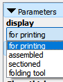
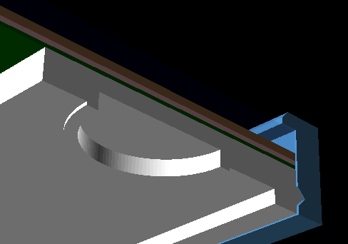
The display field lets you see the model with the pieces separated and in the best orientation for printing, or assembled, or assembled with a cutaway view, as shown above. The “folding tool” option is for cases where you’re folding down the edges of the artwork as in the rainbow picture above — it creates a two-part tool that let you easily fold back the flaps in the exact right places. More about this later.

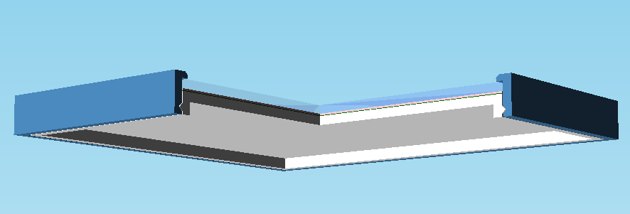
As always with my designs, the views showing how parts are assembled switches to the “for printing” layout when you use the Design > Render function (F6 in Windows), because there’s no use in exporting the parts in their assembled configuration.
Front Matter section
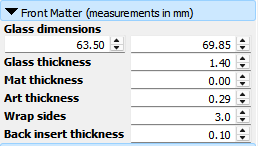
The section of Customizer parameters labeled “Front Matter” gives the sizes of all the things you intend to put into the picture frame. The four “thickness” values are listed from front to back, and any of them can be zero to leave that part out.
The “Wrap sides” setting gives the width of the flaps on the edges of the artwork that you intend to fold down to show through the clear sides of the frame. If using flat artwork without wrapped edges, set this to zero.
Because the tolerances are tight, the assumption here is that the fold-down edges don’t overlap each other, as they would if you folded a flat rectangle and made neat hospital corners with the extra material. This script is designed for artwork shaped like a fat cross, with the corners cut out.
If you wanted to do it the other way, first, please reconsider. Second, if you must, talk to me and let’s figure out how to make the script accommodate it in a reasonable way. If you’re too impatient, you’ll have to figure out how to make the script accommodate it by trickery. You have to allow enough space around the edges for your multi-layered corners, so you could lie and say the art thickness is 3 times the actual thickness of the material. Then lie again and say some other layer is thinner than its actual measurement to make the total thickness come out right.
The “back insert” is an extra sheet of paper behind the artwork that goes to the edges of the frame. If you plan to make an aperture in the back of the frame and put a sticker on the back of the artwork, that doesn’t make the sandwich thicker. In that case you’d enter zero for the back insert.
Frame measurements section
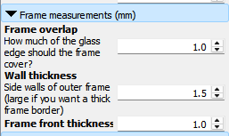
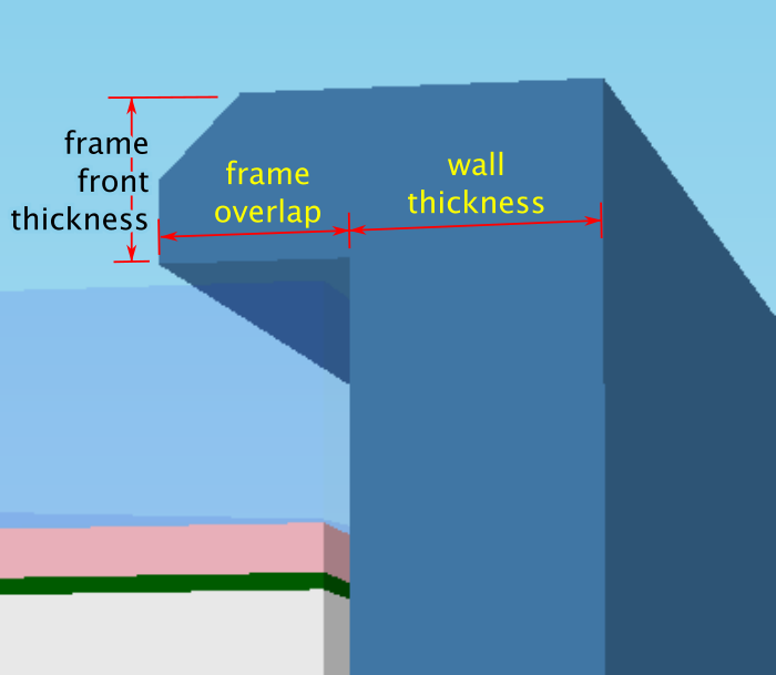
Use the frame overlap setting to set the amount of “lip” at the front of the frame to hold the glass and other parts in place. If you want a wider edge to the frame, the wall thickness can add as much width as you want. The frame front thickness controls how far back the glass is inset from the front of the frame. The bevel is non-optional.
Back measurements section
This section controls the dimensions of the snap-in back piece.

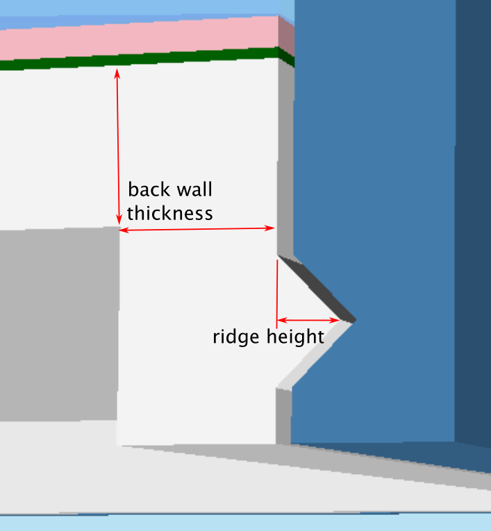
The ridge height setting controls the size of the ridge and the matching groove on the frame, to snap the pieces together. The back wall thickness applies to all the sides of the back piece — it’s essentially a box made of slabs that thick.
Because magnets tend to be small, you can make the piece lighter and thinner without losing much strength, if you embed the magnets somewhat into the back material, so the back is actually thinner below the magnets than elsewhere. The under magnet thickness specifies the minimum thickness of the backing piece where there are magnets, letting you embed the magnets into the back.
The back has to be at least large enough to contain the ridge, the fold-down sides of the artwork if any, the magnet platforms, and the magnets. If it still isn’t as thick as you like, you can set the minimum back height to increase it. The frame thickness will also change if you do this.
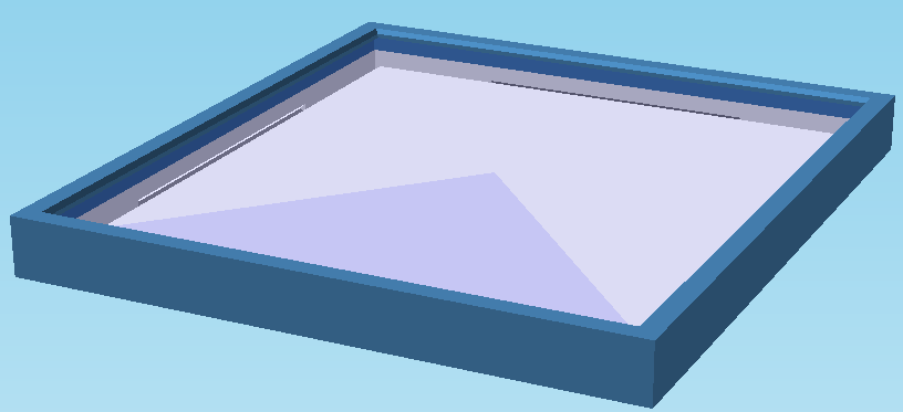
If aperture size is non-zero, it creates a rectangular opening in the center of the back piece, as shown in the photos at the top of this post. If you want it off-center, the aperture offset coordinates reposition it.
Magnets
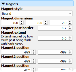
You can optionally add magnets to the back piece. The settings let you select round or rectangular magnets, and create platforms of just the right height to make them flush with the back of the frame. The magnet extend setting lets you make the platforms a little taller so the magnets stick out.
The magnet dimensions settings are the width, length, and depth of each magnet. For round magnets the middle number is ignored.
If you’d like a cup for the magnet instead of just a flat-topped platform, the magnet post border setting controls the thickness of the cup walls. I suggest making the platform a tiny bit larger than the magnet just to avoid it being too tight a fit.
Then the magnet N position settings let you place up to four magnet platforms on the back. The positions are relative to the center of the back. If you need fewer than four magnets, leave the coordinates for the others outside the area of the back, and they will not be added.