Several posts on this website are about 3D-printing objects for use in your gallery, and most of these use OpenSCAD to let you customize those objects by entering parameters for size, text you want to print on the object, etcetera. To avoid repeating information, this page gives general instructions on how to use the OpenSCAD software to generate the information needed to make the 3D printer work.
General Process
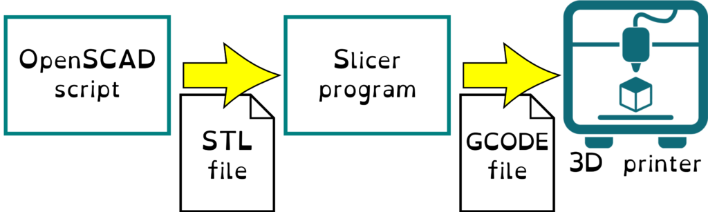
The OpenSCAD script comes in the form of one or more “.scad” files. If there are more than one, typically one of them is the main script that calls functions defined in the others. There may also be “.json” files giving predefined configurations of the parameters you can use to customize the output, or other data files that the OpenSCAD script reads.
To execute the script, use the free OpenSCAD program, installed on your computer. This is available for all home computer operating systems.
Note: Some scripts might be available to run online via the Makerworld.com parametric modeler, but it’s missing some important capabilities, so I recommend using the client software even for scripts you find on Makerworld.
The screen of the OpenSCAD client is divided into various panels:
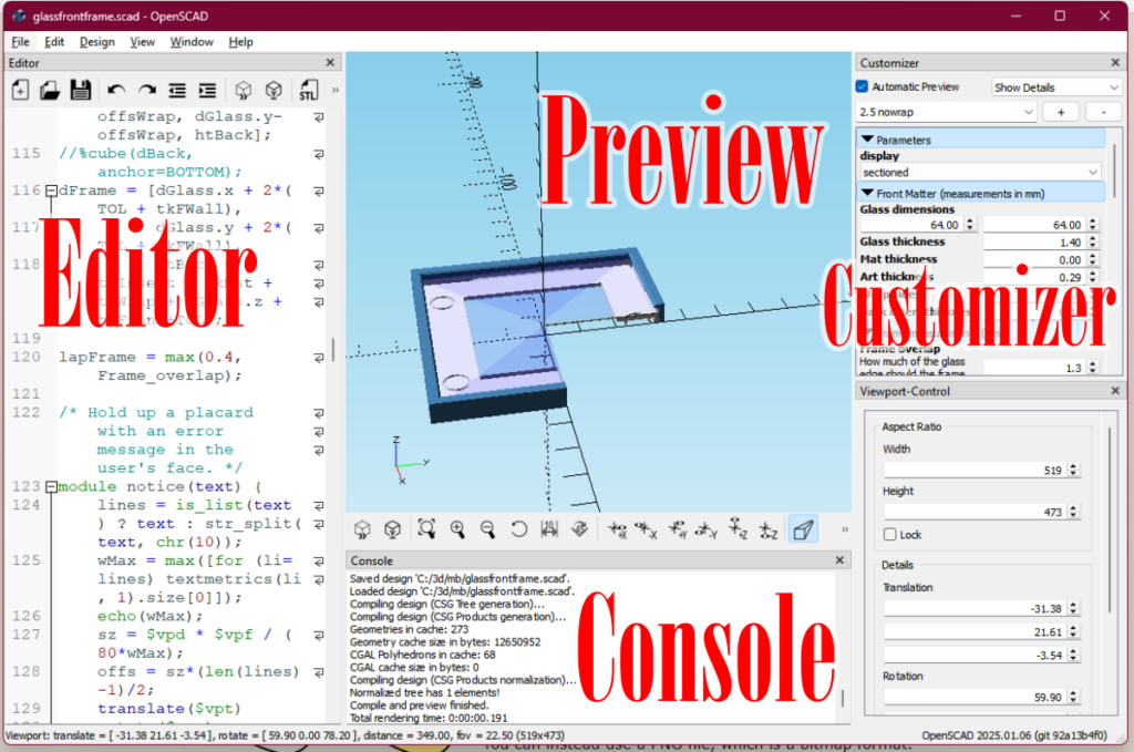
- Editor panel shows the source code of the script. Unless you want to learn the language and take a stab at editing the code, this isn’t useful to you and you can close it to give more space for seeing the…
- Preview panel, which shows what your model will look like. If there are multiple parts involved, as with this picture frame that snaps together, they might be shown assembled, or laid out in the way they need to be printed. This sample shows the parts assembled with a section cut out to let you check for fit.
- Customizer panel offers parameters that let you customize the model; for instance, if the script generates a picture frame, you might specify the size of the picture.
- Console displays messages describing the process of executing the code, and may include error messages or informational messages from the script. If something isn’t working, you may find an explanation here.
Once you have the parameters correctly set to generate the shapes you want, you “render” the model, which converts the quick-and-dirty preview into a more precise representation. Use the menu Design > Render to do this.
A rendered model can be exported into a standard 3D file format (menu File > Export > …). Generally you’ll need an STL file or (less often) an OBJ file to be the input to the next step in the process.
That next step may be to hand someone this file and ask them to print it for you (for instance, my local public library will print STL files patrons email them). You may need to look for any special instructions that came with the script, that they will need to follow to get good results.
If you aren’t fortunate enough to have someone to print it for you, use a slicer program to process the STL or OBJ file into thin layers for printing. I use PrusaSlicer, which is free, but there are several other good slicer programs out there, mostly also free. Desirable features for a slicer program include the ability to adjust where supports are added and to insert pauses and color changes.
Supports are used during 3D printing to deal with the fact that you can’t extrude a strand of melted filament in midair and have it remain in place. It needs support from underneath, which you will break off after the print is completed. Smart design and a good choice of orientation for printing the part, can usually minimize or eliminate the need for supports.
Occasionally, a model will require a manual operation during printing. For instance, if there’s a logo at the top of the model that you want to display in a contrasting color, you can tell the slicer to add a pause at a given height to let you change filament reels (unless you’re fortunate enough to have access to a multi-color printer). Or you may need to pause to insert a metal part into the model, such as a magnet or hex nut, which is then covered over with plastic. If so, the instructions that come with the script should say, but you’ll need to learn how to use your slicer software to know exactly how to do it.
OpenSCAD Installation
To use the scripts you will find on this site, you generally will need a recent “development version” rather than the current “stable” version. The development version is much, much faster and has features that some of the scripts require.
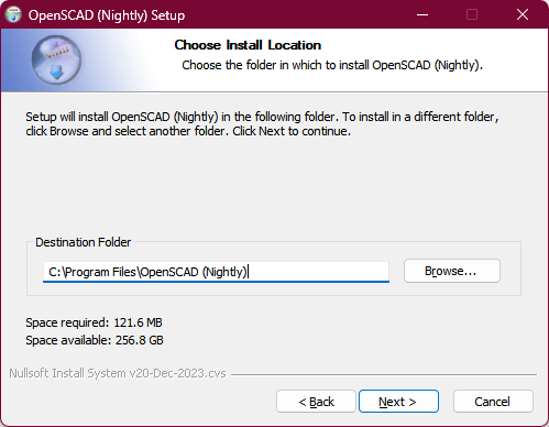
Go to OpenSCAD – Downloads page. Under the Development Snapshots section, download and install the appropriate version for your operating system. I suggest removing “(Nightly)” from the installation path, but in any case, wherever you decide to install it, note that path.
Add BOSL2 Library
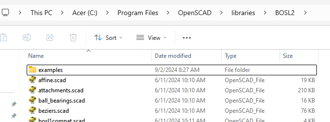
Nearly all of my scripts, and many you’ll find elsewhere, use helper functions from the free BOSL2 library. After OpenSCAD installation completes, visit the installation folder and navigate to its libraries subfolder.
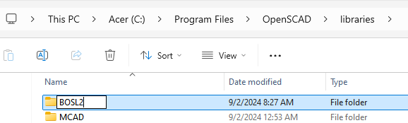
Create a new folder named BOSL2.
Download the zip file at https://github.com/BelfrySCAD/BOSL2/archive/refs/heads/master.zip and unzip or open it. Navigate into the BOSL2-master subfolder.
Copy everything into the BOSL2 folder you created.
Configure the client
Launch OpenSCAD. Use menu Edit > Preferences, then:
- go to Features tab, and enable the features roof, textmetrics, and import-function.
- go to Advanced tab
- In the 3D Rendering section, change Backend field to Manifold (new/fast).
- Under OpenSCAD Language features notice the Stop on the first warning option. Remember where it is, so if you run into a script that goes into what seems to be an endless loop of warnings given some parameter inputs, you can come back and check this box.
Close the Preferences window and close the OpenSCAD program. The new settings will be in effect next time you open it.
Install image editors
Some of these 3D printing projects let you incorporate custom artwork you created. Probably you already have your favorite programs for creating vector-based and bitmap graphics, but if not, here are my picks.
- For creating vector images (SVG files), I recommend Inkscape, which is free.
- For bitmap graphics, I recommend GIMP, current stable version, which is free. OpenSCAD is only capable of importing PNG bitmaps at this time. GIMP can convert existing images into this format.
Running a script
Begin by reading any instructions that accompany the script. In case there are multiple script files, this will tell you which one you should launch to run the program. That script may then load image data or refer to functions in those other files.
If there are multiple files involved, they will be in a compressed ZIP file. Please upzip all the files into a folder where you can maintain their paths relative to each other. The script will use relative filepaths to locate the other files it needs, so they need to be installed with the same folder structure as in the ZIP file.
Open “.scad” files in the usual way — by launching them from a file window, or by opening OpenSCAD first and then using File > Open menu to load them.
Using the Customizer
For scripts I write, I try to make it reasonably obvious what you will affect by changing parameter values in the Customizer panel, but some of these models are complex, with interactions between the different settings, so reading the instructions that accompany the script is a really good idea.
I generally try to make the parameter settings as resilient as I easily can, so that they’ll do reasonable things even if you give them unreasonable inputs, but there are limits to how much I can do there (and other developers might not do as much). There are often multiple parts that have to fit together, and you might be able to enter values that result in ridiculous configurations that wouldn’t work in real life.
That’s why in my designs, if there are multiple parts, I’ll generally provide a selection in the customizer to let you see the parts assembled, often with a cross-section cut out, so you can check the fit or just see how the parts are intended to fit together. Other scripts may not provide this ability, but in any case, look carefully at what it’s asking you, read the prompts, and think carefully to come up with good answers.
A few of my models also include an “object for scale” feature that lets you select a common object — a coin, credit card, banana, etc — to include next to the model to give you an idea how large it is.
A few general principles:
- With rare exceptions, for my scripts and most others, all length measurements are in mm units, and angles are in degrees.
- If asked to specify a color, various color names are recognized, such as “red”, “lightblue”, or “gold”. The system also accepts hexadecimal color codes such as “#d95848” (values for red, green, and blue levels, and optionally two digits for degree of opacity).
- Note: color information is just used for your reference in previewing objects. It isn’t included in the exported 3D model (there are exceptions but if you need to read this document, they don’t apply to you). It’s up to you to choose the right filaments, etcetera, to get the colors you want in your print.
- If there’s text and you can select a font, the menu item Help > Font List shows a list of fonts installed on your system. Use the Copy to Clipboard button in this dialog to get the correct syntax for font name including styling, e.g. “Century Gothic:style=Italic”
- If one of my scripts asks for a tolerance value, leave it at the default value unless you have a printing problem. This is a property of your printer and filament, and refers to the minimum distance apart you have to lay down two lines of filament to have them not touch and stick together. The default value of .15 or .16 works for home printers using the most common nozzle sizes and filament types. Only adjust it if you’re having a problem, such as parts supposed to snap together being too tight or loose.
Exporting the model
When you’re satisfied you have the right parameter settings for what you want to print, use the menu Design > Render (F6 key on Windows) to convert the model to a more precise representation. If there are multiple parts, some things are meant to be printed with parts enmeshed with each other (fidget toys, for instance), but others mean for the parts to be printed side by side or in different materials to be assembled later. You can use the slicer program to separate a single export of multiple parts into different files later, provided there’s a gap between them.
Note: for my scripts, even if you are previewing the model in an assembled or cross-section configuration, rendering will automatically trigger the parts to be rotated and positioned into the best configuration for printing. This is not true of scripts in general.
Next use File > Export… menu to save the 3D model into an STL or OBJ file, which you can then import into your slicer program.
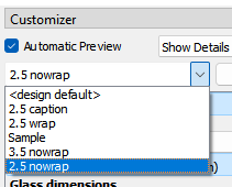
Before you close OpenSCAD, you may want to give a name to the group of configuration parameters you just went to all this trouble to come up with, and save these changes (File > Save menu), so that you can later reload these settings.
Take care not to accidentally modify a saved parameter set. If you want to make a variant which is (let’s say) 3mm wider but otherwise identical, click the “+” button to duplicate the current parameter set and give it new, meaningful name.
Printing advice
In general:
- Think about where supports will be needed. Is there a way you can orient the model to minimize the need for supports?
- The slicer program can automatically generate supports, but sometimes it gets it wrong. Check that it’s not creating supports that will be impossible to remove.
- Consider there are different styles of support available.
- A surface that had a support under it, may often not look as nice as one that didn’t need that. Sometimes you’ll need supports no matter what, but you’d rather have them on a hidden side even if that requires more of them.
- Another consideration for how to orient the model is the amount of surface that will be in contact with the plate. Adhesion of the first layer is crucial to a successful print, because if it comes loose during printing, there’s no way to recover (and you might have been printing for days before that happens). You can have the slicer add extra material to the bottom layer to give better surface contact, but if there’s already a nice big flat side, think about putting that side face down.
- Orientation also should take into account the “grain” of the print. Models are stronger horizontally than they are vertically, because each layer contains continuous strands that don’t break as easily as layers can separate from each other. A long rod should generally be printed lying down, for strength.
- These different considerations may give contradictory answers for how best to orient the model for printing. That would be a design issue, and isn’t something you can always solve in the slicer program. But be creative — maybe the answer is to print it at a slant.
- The slicer can fill up the print bed with duplicates of a model so you can make a bunch of them at once. I suggest you start out with one at a time, to make sure the model is the way you want. You also want to do single prints initially to make sure it prints cleanly. If you print multiples of something and your adhesion to the build plate is marginal, there’s a good chance one will detach during printing and spoil the whole batch. And with a FDM printer — the kind that deposits filament — printing three copies still takes three times as long as printing one, so you’re not really saving as much time as you might think unless the parts are pretty small and quick to print.
- If your prints are messy or come loose during printing, these are the first things to check:
- Are you using recommended nozzle temperature, bed temperature, cooling settings, and speed settings for your filament and printer?
- Is the filament dry? PLA, especially, tends to absorb moisture from the air and that makes it perform badly. Unless you live in Arizona, keep it in a sealed container with gel packs, dry it out as needed (there or filament dryers you can buy, but your oven might also work if you’re careful about the temperature).
- Is the nozzle clogged up or have old burnt filament on its exterior?
- Is your build plate clean? I mean like super clean. Fingerprints, hairs, dust on the plate can cause adhesion failure. I clean mine regularly with isopropyl alcohol and a microfiber cloth. (A heated PEI plate is so much better than a glass plate, BTW.)
- Does your build plate need alignment, or the nozzle Z axis home position need adjustment? (If you’re considering which printer to buy, definitely spring for one with automated alignment.)