This is a guide for how to create 3D-printed pushpin-style magnets for your Free Little Art Gallery, which are useful for hanging artwork if the gallery has magnet-compatible walls. These can be customized with your graphics.
You can:
- Size the magnet hole to accommodate any size cylindrical magnet.
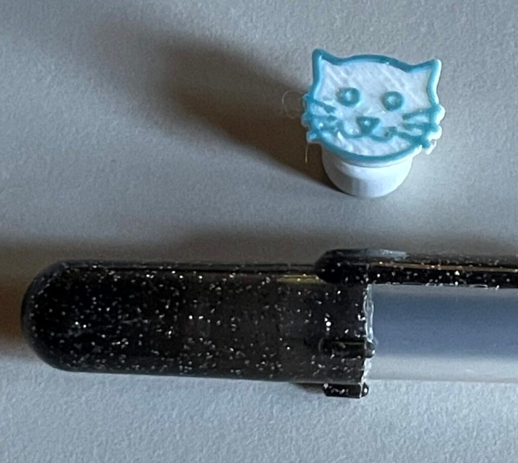
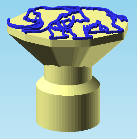
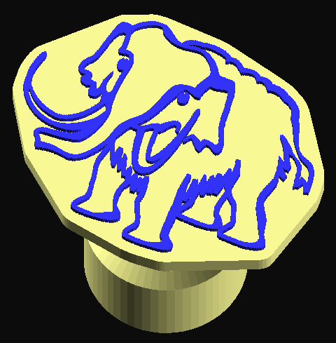
- Add line-art to the pin head like the cat face below.
- Use 3D shape as the pin head, based on an STL or OBJ file you’ve downloaded from any online library of 3D models.
- Make a simple flat head like a regular push-pin.
The model is designed to let you either leave an opening in the base to glue magnets in after printing, or completely enclose the magnets in the model by inserting them during printing. Embedding the magnet reduces its holding power compared to making direct contact with the wall.
As pictured above, when using line art, the result looks best if the raised lines are printed in a different color than the rest of the pin. If your printer doesn’t automatically do multi-colored prints, use your slicer program to insert a color change, so the printer will pause to let you change filament reels before it prints those last couple layers.
These magnets are awfully cute and people may swipe them from your gallery. I feel this is in keeping with the spirit of Free Little Art Galleries — I just think of them as more art that people can take home. Print extra to replace those that walk off.
How this works, big picture
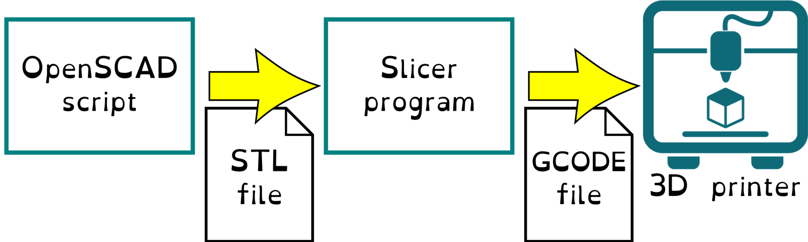
I’ve written about the general process for using OpenSCAD scripts to make customized versions of models, so I won’t repeat all that here. There’s an extra step involved for these models, in that you need to prepare your customized graphics as an import file, from a limited set of file formats, and supply the name of that file to the script as a Customizer parameter.
You start out with the 2D artwork for the pin head, in the form of a SVG file (preferred) or a PNG file. Or you can use an STL or OBJ file to make a 3D pin head.
Preparing the artwork
Your custom graphics or 3D shape are imported from a separate file whose name you provide to the OpenSCAD script.
2D Artwork

The file you import for a line-drawing pinhead — like the kitty-cat — should be single-color vector art, preferably an SVG file, containing one closed Path object (though the path might have multiple separate parts).
You can instead use a PNG file, which is a bitmap format. If you do this, the script will try to translate it automatically to an outline based on a brightness cutoff. This works well with clean line art — less well with images that contain more color values. There’s a parameter in the script to adjust the brightness threshold, but some artwork doesn’t convert very well. In that case you must produce the SVG file yourself. This you can do by importing the image into a vector drawing tool, such as the free Inkscape program, and using the tools there to “convert “trace” the image.
For tiny magnets like the kitty shown above, simple images with thick lines work best. The larger the “head” of the pin is, the finer details you can see in the result. Use your judgment and consider the capabilities of your materials and printer.
To use a bitmap file that’s not a PNG
The script supports import of PNG images. If the file you have is a different bitmap format — JPG, WEBP, HEIC, or GIF, for instance — you will need to convert it to a PNG file.
This is easy to do with a bitmap editor, such as Windows “Paint” or the excellent free tool GIMP. Open the file in your chosen program and “Save as” a PNG file (or in the case of GIMP, “Export As”).
3D Artwork
If you have an STL or OBJ file, enter the filepath in the “filename” field and see how it turns out. The object will be imported and scaled so its X-dimension matches the “top width” you specify. In the “if 3D export” of the settings, you can rotate it about the X axis to make it face up, then adjust the Z scaling (often you’ll want to flatten the shape).
For 2D artwork, slopes are added to prevent the back side of the pin head from facing straight down, which is called an overhang. Since you can’t lay down filament in midair, this requires a support structure to print. If you use a 3D shape, the script can’t do this for you automatically — it’s up to you to decide whether to do something to eliminate overhangs. If you do nothing now, that’s fine — you’ll have to make sure the slicer program generates supports to prevent problems during printing.

If you want to add your own cone shape to your STL file so the model prints cleanly with no supports, this isn’t too hard to do in a simple 3D CAD system, such as Tinkercad. Or you can increase the post diameter and/or wall thickness settings to try to engulf all the overhangs in support column. The result would no longer look like a pushpin, but that’s your call.
Import errors for STL files
If your 3D pinhead doesn’t appear anywhere in the work area, check the OpenSCAN “Console” and “Error-Log” panes for error messages. Some 3D files you download from websites, might not be “clean” — they might contain weird geometry that fails to import to OpenSCAD.
You can generally fix these by importing them into Tinkercad, then exporting as a new STL file.
If there are no errors, but the object still doesn’t appear, it may be far away from the origin. Use menu View > View All in OpenSCAD to make sure the frame includes all objects. It’s also possible your object is in the negative Z space, where the script would cut it off. Enter a large positive Z value into the top offset parameter to raise it into view.
Using the Script
Download and unzip this compressed file, putting all the contents in a single folder on your computer.
Open the file flagnets.scad in the OpenSCAD client. I’m assuming you know the basics of how to use OpenSCAD to run a script and adjust parameters in the Customizer pane.
The default design shown in the customizer is for a simple pushpin shape with no artwork. You might look through the presets I’ve created to see configurations with different image files, some with enclosed magnets and some with holes to insert magnets later.
Customizer Parameters
All measurements are in mm.
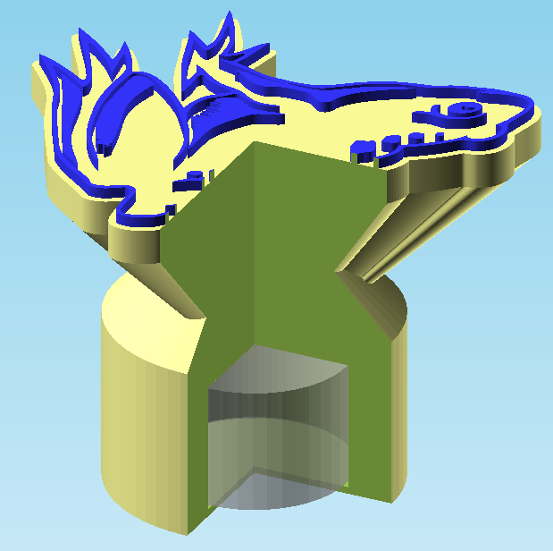
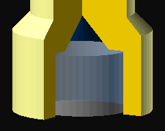
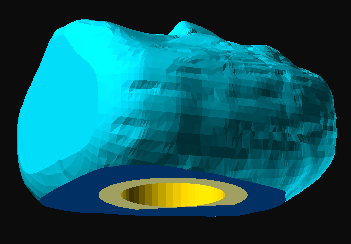
I’ll review the customizer settings from first to last, with one exception: look first at the very end of the panel for the “section” checkbox. This option produces a cutaway view like the second image in this post, and may be helpful in confirming that the magnet is buried at the depth you intended. Otherwise, here are the settings:
Import settings
Filename is the filepath of your import file. All the presets use a relative path, but if the file isn’t in the same folder as the script, you can enter a full filepath here.
Top width is the width of the pin head — the X dimension. The Y dimension, and Z if it’s a 3D file, are automatically adjusted to maintain the ratio of dimensions. There’s a setting further down to flatten a 3D object.
Top offset lets you adjust the position of the pin top in three dimensions. For 2D art, it’ll generally import off center, so you should adjust it. It’s easiest to tell whether the top is centered if you use the bottom view (Ctrl+5).
For 2D art you generally should only adjust the first two values, representing X and Y offsets. For adjusting the height of the pin, use the post height setting. With 3D art, however, it might be far from the origin in all dimensions, so you’ll need to use all three numbers.
If 2D import
This section of settings applies if your import file is an SVG or PNG file — flat artwork. At this point you may want to think ahead to what printer settings you’ll use, in particular the layer height. You need to think in multiples of layer height to know how many layers thick your line art will be.
A normal layer height for most printers is .15 mm. This is fine enough that most prints look pretty good, but not so fine that they take inordinately long to print because of the many layers. If you’re changing the filament color during printing to make the line art stand out, you should generally select a pattern height of .3mm — the default. Some filaments aren’t quite opaque enough for a single layer to do the job. Especially light-colored filaments laid on top of darker ones.
The platform height setting refers to the solid area below the raised lines. It really just needs to be tall enough to grip easily. Remember there’s a slanted area below it, which adds strength.
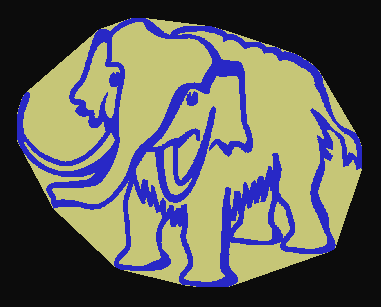
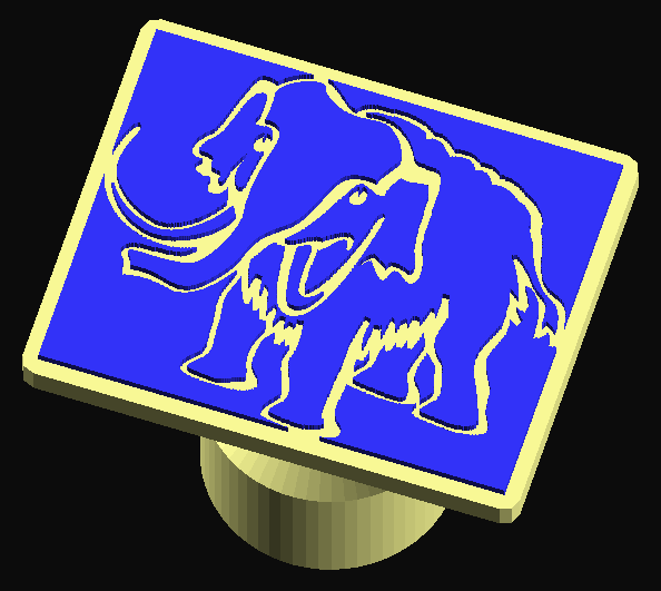
The outline style setting is about how to fill in the background area of the picture. The three choices are depicted below.


Each of these options can be modified by adding extra space around the line art, giving some margin around the edge. That’s done with the outline enlarge setting.
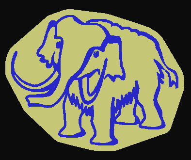
The “hull” setting draws an outline just big enough to enclose the entire drawing, plus your specified outline, with no concave sides. It’s as if you put a rubber band around it.
The “fill” option makes a platform that fills in those areas that are fully enclosed by the lines. If there’s a gap around the outer edge, the results aren’t so great. Even with this friendly mastodon, there are a lot of pointy bits that makes “fill” a less than ideal option for this shape.
The “disk” setting creates a disk whose diameter is the top width you specified above. Often this isn’t big enough to contain the whole image, in which case bumps are added around the edge to support any protrusions, or you can use outline enlarge to make the disk bigger.
The trace threshold setting applies to PNG files. By default, the figure/ground cutoff is at the 50% value between the darkest and lightest pixels in the image. For simple line art this is generally fine, but if you’re not happy with the result, adjust this slider. Be patient — the trace function is slow to calculate.
The PNG import assumes the lines are darker than the background. If the reverse is true — as it might be for a photo of a light object on a dark background — check the trace invert box.
If 3D import
When importing an STL or OBJ file, the settings in this section apply.
Use the rotation setting to make the object face upwards. The measurement is in degrees; if zero isn’t right, try -90 first.
The z scale setting is applied after the rotation, and lets you squash the object in the Z dimension to make it more like a flat pin head. A value of 1 means no distortion — otherwise use a value between 0 and 1.
Once you have the head the orientation and shape you wanted, you’ll probably need to go back up to the top and change the top offset.
Post dimensions
This section controls the magnet enclosure in the base, and the shaft that connects the magnet part to the head.
The magnet embed is the thickness of plastic below the magnet. To make the bottom open, set this to zero. Otherwise, unless the magnet is pretty large, set it to the height of the first layer of your print, often 0.2mm, so the magnet will be as close as possible to the outside.
Note: it’s for you to decide, when creating the GCODE file in your slicer, how thick the first and subsequent layers of your print will be. Typically the first layer is thicker than the rest, to provide good adhesion to the build plate. Most commonly the base is 0.2mm and subsequent layers 0.15mm. Because these magnets tend to be on the small side, you might choose to use a finer layer height to get better rendering of details, particularly if you use a 3D pin head.
If your magnet is really large and strong you might want to enter a number here that’ll result in a thicker base layer, but one layer is enough for magnets of the size you would usually use in a FLAG.
magnet_diam is the diameter of the magnet. Add a little to the actual measurement — 0.2mm or more — to allow for the fact that 3D printing is less precise than machined parts. The default value fits these magnets you can order from Amazon (affiliate link).
magnet_height is the height of the magnet — which is to say, the depth of the hole in the pin base. The default value here is the height of two magnets of the type mentioned in the previous paragraph, since I’ve found one is too weak to rely on for holding artwork to the wall, particularly when, as in the case of my FLAG, the wall is magnetic because of magnetic paint rather than being made of sheet metal.
The post_height setting is the height from the base of the magnet to the bottom of the platform (for 2D art). So the total height of the model for 2D art is post height + platform height + pattern height. For 3D art, the total height depends on the size and positioning of the pin head you import.
post_diameter is the diameter of the shaft that connects the top of the magnet to the base. It will generally be less than the base diameter, but that’s up to you.
wall thickness refers to the thickness of the sides of the base, around the hole that contains the magnet. So the base diameter is magnet diam + 2*wall thickness.
peak in magnet hole option applies only if the bottom is open. It selects whether to give the magnet hole a pointy roof with a little ledge for the magnet to rest on, as opposed to a flat roof. This is a good option when using a larger magnet. It helps with printing by requiring less support material and making the support easier to remove. It does use more glue that goes into the hole, if you’re sloppy with it. Your call.
Advanced settings
The only setting here is as described above, the section checkbox that temporarily takes a slice out of your model so you can check the interior.
Printing Considerations
There are special considerations for printing these models:
- Inserting a pause for filament color change, to create line art in a contrasting color.
- If the bottom is closed:
- Whether (and how) to skip print supports for the roof of the magnet hole, without also eliminating supports needed elsewhere.
- Insert a pause for adding magnets during the build, while the holes are still open on top.
If bottom is open
Enable automatic supports in the slicer and see whether it wants to create any supports. Unless the magnets are very small, this will create supports in the magnet hole. These are a nuisance to remove, so you might override this, remove those supports and test whether it prints okay.
The flat roof of the magnet hole is what’s referred to as a “bridge” — it’s got support on either end, so depending on the material, nozzle temperature, and the distance spanned, you might be able to get away with stretching the filament across that gap. Your slicer program might have an option to not generate supports for bridges, or you might have to manually mark that area off limits. Not all slicer programs have features that’ll let you do this.
The peak in magnet hole option might help in the case of larger magnets. At least it’ll only need support around the edges of the hole in that case.
If bottom is closed
You will have to use a slicer program capable of inserting pauses in the GCODE file so you can add magnets and resume printing. Some printers may require custom coding for this, as described in my Sovol cheat sheet.
Since you need the hole empty to insert a magnet during printing, avoid generating supports inside the hole. They’re nearly impossible to remove during printing without wrecking the print, and they’re not needed, even for large magnets, because the magnet is your support for the roof in this case.
If using 2D artwork, no other part of the model needs support, so you can just turn off auto-generated supports.
If importing a 3D pin head that hasn’t been designed to not need supports, there are a couple of different approaches you can try. These depend on PrusaSlicer options which may be called something different in other slicer programs, if they even exist:
- Leave auto supports off and “paint” supports where needed.
- Turn on auto supports and also enable “Support on build plate only” or “Don’t support bridges”, either of which will prevent the magnet hole getting filled with supports, while allowing support for overhanging parts of the pin head.
You can also eliminate the need for support in some cases by using the “top offset” Z setting to lower the head until it engulfs the magnet and flattens out against the print plate, as shown in the “zardoz flush” preset. If you do that it might still be a fridge magnet, but it’s not a pushpin magnet.
For the nerds in the audience
The script contains a couple of hidden parameters for a “support cone” for 3D objects. This creates a downward-pointing cone that sticks out the back of the object to at least reduce the amount of support that’s needed. However, the shapes of imported objects are so unpredictable, that it’s hard to design a general-purpose support structure that’s never going to protrude from the sides of the object. That’s why these settings are hidden, but if you want to edit the script to unhide them, be my guest. They belong in the “if 3D import” section of parameters. If you really want your pin head to print without supports, it’s probably best to design it so yourself.